


How to Choose the Right Vibrating Feeder | UK Guide

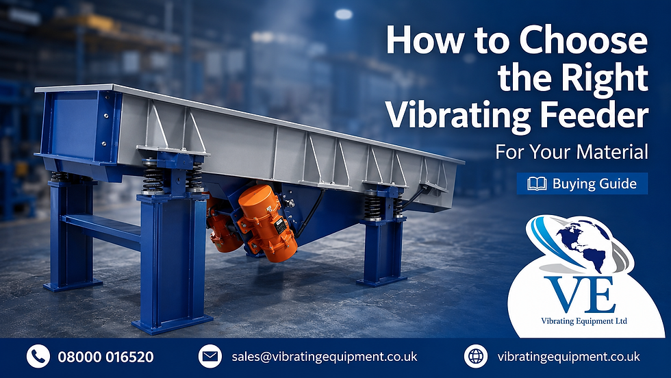
Choosing a vibrating feeder is not simply a matter of selecting the largest machine or the most powerful vibrator motor.
The correct feeder must be matched to the material, required feed rate, operating environment and surrounding production equipment. A machine that performs well with dry plastic granules may not be suitable for damp powder, abrasive aggregate or fragile food products.
A properly specified vibrating feeder provides a controlled and consistent supply of material into downstream equipment such as conveyors, screens, crushers, mixers, weighers and packaging machinery. Vibrating Equipment Ltd designs feeders for powders, granules, aggregates and smaller industrial components across a wide range of processing applications.
This guide explains the main points to consider before selecting or requesting a quotation for a vibrating feeder.
Start with the material being handled
The material is the most important part of the specification.
Two materials that appear similar can behave very differently when subjected to vibration. Before choosing a feeder, consider the following characteristics.
Particle size and distribution
Record the smallest, largest and average particle sizes.
A material containing particles of a similar size will normally behave more predictably than one containing a mixture of fine powder and large pieces. Fine particles may settle between larger particles, separate during movement or compact inside the trough.
Where accurate dosing is required, the complete particle size distribution should be considered rather than relying only on the largest particle size.
Bulk density
Bulk density affects the weight of material carried by the feeder at any given time.
A trough containing lightweight cereal pieces places a very different load on the drive system from the same trough filled with sand, metal components or dense mineral material.
The manufacturer needs the loose bulk density, normally expressed in kilograms per cubic metre, to estimate the working load and expected capacity.
Flowability
Free flowing granules generally move more easily than cohesive powders.
Fine powders may bridge, form lumps, retain air or resist movement. Irregular flakes and shredded materials can interlock. Long fibres may catch against edges or form a stable layer across the trough.
Describe any existing flow problems when requesting a quotation. A short video of the material leaving its current hopper can be particularly useful.
Moisture content
Even a small change in moisture can alter how a material flows.
Dry sand and damp sand do not behave in the same way. A powder that flows well in laboratory conditions may become cohesive in a humid factory environment.
Where moisture varies throughout production, provide both the normal and worst case conditions.
Product temperature
Hot, frozen or temperature sensitive materials may require a particular trough material, insulation system or surface treatment.
Thermal expansion must also be considered where the feeder handles material at a substantially different temperature from its surroundings.
Fragility
Biscuits, coated confectionery, cereals, plastic components and similar products may be damaged by excessive vibration, steep drops or unsuitable trough surfaces.
For fragile materials, the feeder should move the product with controlled acceleration and minimise unnecessary transfer points.
Abrasiveness
Sand, minerals, glass, metal fragments and other abrasive materials can gradually wear the trough.
A wear resistant liner, replaceable impact section or heavier plate construction may be required. The correct solution depends on the material, particle size, feed rate and point of impact.
Define the required capacity correctly
Capacity should normally be stated as a mass flow rate, such as kilograms per hour or tonnes per hour.
It is useful to provide:
The normal operating rate
The minimum required rate
The maximum or peak rate
Whether feeding is continuous or intermittent
The expected number of operating hours per day
The amount of material held above the feeder
Do not specify capacity based only on the output of the downstream machine. Allow for start up, changes in production speed and short periods of increased demand.
The feeder may also need to operate across a range of feed rates. This is particularly important when supplying weighers, batching systems or packaging machinery.
Consider the pressure from the hopper
A feeder installed beneath a hopper may be exposed to significant material pressure.
This is often described as head load.
Excessive head load can restrict material movement, overload the trough or cause an uncontrolled initial surge when the feeder starts. The outlet size, hopper geometry, material depth and gate position all influence this load.
The transition between the hopper and feeder must allow material to enter without clamping the vibrating trough or preventing free movement.
Flexible connections must also be arranged so that they contain the material without creating excessive resistance.
Choose the appropriate drive system
Two common feeder drive arrangements are electromagnetic drives and rotating vibrator motors.
Electromagnetic vibrating feeders
Electromagnetic feeders are often selected where responsive feed control is important.
They can start and stop quickly and are suitable for applications requiring frequent adjustment, batching or controlled dosing. The feed rate can normally be altered through a suitable electromagnetic controller.
They are commonly used with smaller and medium sized troughs, although final suitability depends on the complete design and required duty.
Vibrating Equipment Ltd currently supplies LEV electromagnetic linear feeder drives for controlled material feeding applications.
Motor driven vibrating feeders
Motor driven feeders use one or more rotating vibrator motors to create the required movement.
They are commonly considered for larger troughs, heavier materials, continuous feeding and higher capacity applications. Depending on the machine design, speed control may be achieved through a suitable variable frequency drive.
OLI’s standard external vibrator range includes 2, 4, 6 and 8 pole motors for feeders, conveyors, screens, compaction tables and other vibrating machinery. The available centrifugal force is adjustable within the limits of the individual motor.
The drive type should not be chosen in isolation. Trough mass, material load, spring arrangement, operating frequency, required movement and support structure must all be considered together.
Select the correct trough design
The trough should suit both the material and the production environment.
Open trough feeder
An open trough provides straightforward access for inspection and cleaning.
It is suitable where dust containment is not critical and the product does not need complete protection from the surrounding environment.
Enclosed tube feeder
A vibrating tube feeder provides greater containment for powders, fine granules and dusty materials.
It can reduce spillage and protect the product during transfer. Connections at the inlet and outlet still need to be properly engineered, especially where dust control is critical.
Vibrating Equipment Ltd manufactures enclosed vibrating tube feeders for powders and granules requiring controlled, low spillage transfer.
Stainless steel trough
Stainless steel is often selected for food, chemical, pharmaceutical, wet or corrosive environments.
The required grade and surface finish should be based on the product, cleaning chemicals and operating conditions. Stainless construction alone does not automatically make a machine hygienic. Frame accessibility, weld finishing, drainage and cleanability must also be considered.
Lined trough
Replaceable liners can protect the main trough from wear, reduce noise or prevent material from sticking.
Possible lining materials depend on temperature, abrasion, chemical compatibility and hygiene requirements.
Decide how the feed rate will be controlled
A feeder may need more than a simple start and stop switch.
Possible control arrangements include:
Manual feed rate adjustment
Electromagnetic controller
Variable frequency drive
Timed batch control
Level sensor control
Weigher or load cell integration
Programmable logic controller integration
Upstream and downstream equipment interlocks
For example, a level sensor can stop the feeder when a downstream hopper is full. A weight controller can slow the feeder as the target batch weight is approached.
The required control method should be agreed before the machine is manufactured.
Check the available production space
Provide accurate site dimensions and identify all surrounding equipment.
Important measurements include:
Inlet height
Outlet height
Available feeder length
Available width
Supporting steelwork
Access required for cleaning and maintenance
Position of electrical controls
Nearby walls, columns and walkways
A feeder cannot operate correctly if the vibrating section touches rigid pipework, guards, support frames or surrounding machinery.
Allow enough space for the full movement of the machine and for removal of motors, springs, liners and covers during maintenance.
Consider hygiene and cleaning
For food and other hygiene sensitive applications, the machine should be designed around the cleaning method.
Confirm whether the feeder will be:
Dry cleaned
Vacuum cleaned
Wiped manually
Washed with low pressure water
Subjected to intensive washdown
Cleaned with aggressive chemicals
Open profiles, accessible food contact surfaces and well finished welds can reduce cleaning time and make inspection easier.
Electrical equipment, bearings, cables and enclosures must also suit the cleaning environment.
Consider dust and hazardous materials
Fine powders may require an enclosed feeder, extraction connection or controlled flexible joints.
Where combustible dust or another hazardous atmosphere may be present, the complete installation must be assessed by a suitably competent person. Motors, controls and electrical components must be selected for the relevant zone and material characteristics.
Do not assume that a standard enclosed trough automatically creates a dust safe system.
Use material testing for difficult applications
When material behaviour is uncertain, testing with a representative sample is often the most reliable approach.
The sample should reflect normal production conditions, including moisture, temperature, particle size distribution and any coating or surface treatment.
Testing can help determine:
Whether the product moves consistently
The required trough angle
Suitable vibration settings
Likely feed rate range
Whether material separates during movement
Whether a liner is required
Whether the product is likely to bridge or build up
A short test can prevent an unsuitable machine from being designed around incorrect assumptions.
Common feeder selection mistakes
Several recurring mistakes lead to disappointing feeder performance.
Selecting by trough size alone
Two feeders with the same trough dimensions may have completely different capacities because of their drive, angle, material load and operating frequency.
Ignoring variations in the material
A feeder specified using a dry sample may perform differently when the production material becomes damp, warm or compacted.
Providing only an average throughput
The machine must be capable of meeting the actual operating range, including peak production demand.
Restricting the vibrating section
Rigid inlet sleeves, tight outlet connections or incorrectly fitted guards can prevent free movement.
Choosing the motor before designing the machine
The vibrator motor must be selected as part of the complete dynamic system. It should not be chosen from centrifugal force alone.
Failing to consider cleaning and maintenance access
A machine may fit into the available space but still be difficult to inspect, clean or repair.
Information required for a vibrating feeder quotation
Provide as much of the following information as possible:
Material name and description
Minimum and maximum particle size
Bulk density
Moisture content
Product temperature
Required feed rate
Continuous or batch operation
Inlet and outlet dimensions
Available length, width and height
Construction material
Open or enclosed trough
Required controls
Electrical supply
Cleaning method
Hazardous area requirements
Photographs or drawings of the installation
A representative product sample where testing is needed
Frequently asked questions
Can one vibrating feeder handle several materials?
Possibly, but the materials must have reasonably compatible flow characteristics. A feeder optimised for a dense, free flowing granule may not provide the same performance with a lightweight cohesive powder. Each material should be reviewed before the feeder is specified.
Can the feed rate be adjusted?
Yes. The appropriate method depends on the drive system. Electromagnetic feeders use a compatible controller, while some motor driven systems can use a suitable variable frequency drive.
Can a vibrating feeder be manufactured in stainless steel?
Yes. Stainless steel feeders can be supplied for food, chemical, wet and corrosive environments. The grade, surface finish and overall hygienic design should match the application.
Is an enclosed tube feeder always better for powder?
Not always. A tube provides improved containment, but access, cleanability, product build up and connection arrangements must also be considered.
How is vibrating feeder capacity calculated?
Capacity depends on material bulk density, trough dimensions, bed depth, vibration characteristics, trough angle and material behaviour. Testing may be needed for difficult or unusual products.
Speak to Vibrating Equipment Ltd
Vibrating Equipment Ltd designs and manufactures bespoke vibrating feeders for powders, granules, aggregates, food products, recycled material and industrial components.
To discuss an application, provide the material details, required feed rate, available layout and any existing production problems.
Telephone: 0800 001 6520


Comments